Layers of CAN Protocol
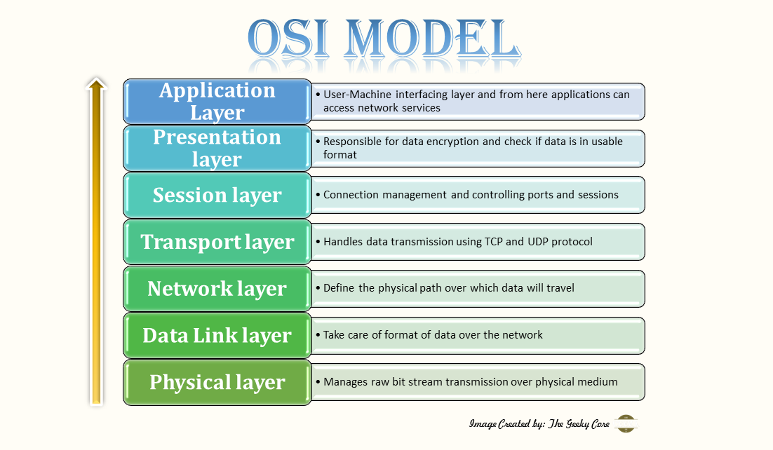
Before diving deep into CAN layered architecture we must have a basic idea of the OSI model . OSI is the acronym for Open System
Interconnection model which standardizes and lays
the foundation for any of the communication functionality in telecommunication and
computer network systems.
It is a seven-layer model and designed to implement a diverse communication system that follows the standard communication protocol.
A simple diagram to represent the OSI model is as below.

Now coming back to CAN, since it is a communication protocol so it is also based on and follows the OSI model. The whole communication
protocol is based on the two layers of the OSI model.
These two layers are as below:
- Data Link Layer
- Physical Layer
CAN Protocol Layers:
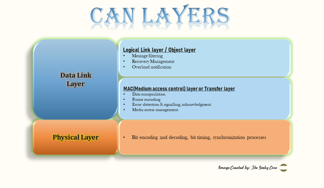
Now as we are familiar with the place of CAN protocol in the OSI model we will look into more detail inside the CAN protocol layers. The CAN functionality of the Data link layer is further
subdivided into two layers.
These sub-layers of the Data link layer are as below:
- Logical Link layer or Object layer
- MAC (Medium access control) layer or Transfer layer
Detailed layered model of CAN protocol can be shown as below:

The working of each layer can be explained as below:-
- Logical Link layer: This layer is responsible for accepting the messages by filtering process, overload notification and recovery management tasks.
- MAC layer: This layer performs the activities like data encapsulation, frame coding, media access management, error detection and signalling and
acknowledgment
tasks. This layer represents the kernel of the CAN protocol. - Physical Layer: This layer mainly deals with the bit encoding and decoding, bit timing, synchronization processes.
Properties of CAN:
There are certain properties of the CAN which play a vital role in setting up the CAN network. These properties are as follow:
- Multicast reception with time synchronization: Multiple nodes can receive the message frame simultaneously.
- Multimaster: Any of the ECU connected in the network may start to transmit a message whenever the CAN bus is free.
- Message Prioritization: According to the importance the priorities will be assigned to the different messages
- Arbitration: In the case when 2 or more units start transmitting messages simultaneously, the unit which gets the bus access will depend on
bitwise arbitration
using the identifier. The mechanism of arbitration guarantees that neither information nor time is lost. - Automatic retransmission of corrupted message as soon as CAN bus become idle.
- Error detection and signalling
- Flexibility in Configuration: In the CAN network, depending on the requirement any number of nodes can be added or removed from the system
without doing
any modification in software or hardware parts. - Acknowledgement: After receiving a message, the receiver node will check the consistency of the received message and acknowledge a consistent
message and
flag an inconsistent message. - Distinguishing between temporary errors and permanent failures of nodes and autonomous switching off the defect node.
- Sleep and Wakeup mode: In order to reduce the power consumption CAN-device may be set into sleep mode without any internal activity and with
disconnected
bus drivers. - Data Consistency
- Message Routing: The message content is indicated by an identifier. This identifier does not indicate the message destination, but it describe
the purpose of the
message, so that it will be easily filtered by the nodes in the network and the correct node will act on it. - Bit Rate: The speed of the CAN is measured in bit rate i.e. number of bit transmitted per second and this bit rate varies from system to system.